This post will outline the bringup of Linux on a PCB I developed from scratch. You can read more about the hardware design in the earlier posts linked above. I’ll talk about driver bringup, system characterization, testing, and software development. By the end of this post, we will have a fully booted single-board computer (SBC). The last post was left on a somewhat unexciting note. To recap, I populated the 2.5V regulator with a 3.3V. After powering up the board, I read this rail had an absolute maximum rating of 2.7V. Or so we were told…
After replacing the regulator with a 2.5V variant, I fired everything up, and the current consumption looked reasonable. I cloned the Buildroot repository to have a poke around. Buildroot is an open source project designed to make building the bootloader, kernel, operating system and required apps easier. The A33-OLinuXino has similar hardware to my board, so I used that as a jumping-off point. There’s one command to configure the build: make olimex_a33_olinuxino_defconfigthis takes the config fromconfig/olimex_a33_olinuxino_defconfig and replaces the .config file in the buildroot home directory. The .config file is responsible for defining the top-level buildroot configuration. Issuing make menuconfig will bring up the config menu.
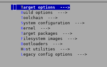
Pictured above is the main Buildroot config that allows you to select things like processor architecture, bootloader, kernel version and packages you want to ship with your image. I built using the vanilla OLinuX config file and flashed output/images/sdcard.img to an SD card, connected my USB to serial converter to the UART pins of the board, inserted the SD card to the board and fired it up…
U-Boot SPL 2019.04 (Jun 23 2021 - 15:19:43 -0700)
DRAM: 1024 MiB
Failed to set core voltage! Can't set CPU frequency
Trying to boot from MMC1
MMC: no card present
spl: mmc init failed with error: -123
SPL: failed to boot from all boot devices
### ERROR ### Please RESET the board ###
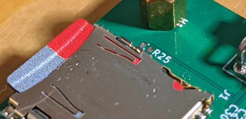
This is the bootloader complaining about something. After a visual inspection of the board, I noticed that I missed populating R25, a resistor in series with the SD detect pin. The SD detect pin is a contact that closes when an SD card is inserted. The contact status can alert the user about a missing SD card, like above with the “MMC: no card present” message.
After popping the part, we got a little farther in the boot process.
U-Boot SPL 2019.04 (Jun 23 2021 - 15:19:43 -0700)
DRAM: 1024 MiB
Failed to set core voltage! Can't set CPU frequency
Trying to boot from MMC1 U-Boot 2019.04 (Jun 23 2021 - 15:19:43 -0700) Allwinner Technology
CPU:   Allwinner A33 (SUN8I 1667)
Model: Olimex A33-OLinuXino
DRAM:  1 GiB
initcall sequence 7efcf0f4 failed at call 4a002459 (err=-5)
### ERROR ### Please RESET the board ###
This error comes from a function in u-boot/include/initcall.h which is responsible for calling a bunch of functions; those function’s pointers are held in two separate arrays called init_sequence. There are two arrays because there are two bootloaders. The primary bootloader sits in the RAM of the A33 itself, which is about 32k. The job of the primary bootloader is to get the secondary bootloader into external ram and run it. We don’t put the entire bootloader into the internal 32k because it won’t fit.
Back to the error itself, 4a002459 is the address of the function that is returning -5 as the error code. To get the symbol from the address, we can grep for it in the address map file. I found it was erroring out on a board_init function, specifically on an i2c function. I had no idea why the bootloader was doing anything with i2c until I remembered the difference between my board and the OLinuXino board: PMICs. The power management IC used on the OLinuXino board was an i2c controlled device with adjustable outputs, while I’m using normal switching regulators. I then went into the uboot menuconfig by issuing make uboot-menuconfigand disabled everything relating to AXP22*, which is the name of the PMIC. I then got to boot and ended up here. After enabling some more verbosity, I found this function was erroring out and printing: “no support for card’s volts”. Without knowing much, I guessed this was more to do with the PMIC, so I ripped out everything to do with it from the device tree file. Before I knew it…
The System Boots!
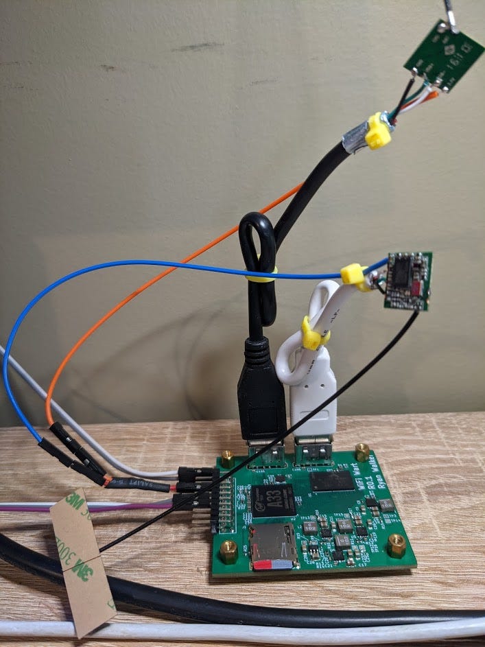
I loaded up the build will all the standard stuff: python, wpa_supplicant, apache web server, the RTL8188eu driver, dhcpcd, dhcpd, vim, and whatever else my little heart could think of. My next goal was to get the two wifi chips up and running. As I couldn’t actually get my hands on the dongles, I had to improvise…
This is actually a preferable alternative to dongles, as those modules run off 3.3V rather than 5V, which is the same configuration as the final design. This means that I can ensure the 3.3V regulators don’t crap out when these guys are going full boar. I then probed in the driver with the modprobe command and found the two wifi devices wlan0 and wlan1 come up right away.
# ls /lib/modules/5.0.0/extra/
8188eu.ko
# modprobe 8188eu.ko
[   86.120509] 8188eu: loading out-of-tree module taints kernel.
[   86.201962] RTW: rtl8188eu v5.2.2.4_25483.20171222
[   86.239880] RTW: hal_com_config_channel_plan chplan:0x08
[   86.246164] RTW: rtw_regsty_chk_target_tx_power_valid
[   86.278995] RTW: hal_com_config_channel_plan
[   86.295988] usbcore: registered new interface driver rtl8188eu
# ip addr
1: lo: <LOOPBACK,UP,LOWER_UP> mtu 65536 qdisc noqueue qlen 1000
    link/loopback 00:00:00:00:00:00 brd 00:00:00:00:00:00
    inet 127.0.0.1/8 scope host lo
       valid_lft forever preferred_lft forever
2: **wlan0:** <NO-CARRIER,BROADCAST,MULTICAST,UP> mtu 1500 qdisc
    link/ether 28:f3:66:44:b1:b1 brd ff:ff:ff:ff:ff:ff
3: **wlan1:** <NO-CARRIER,BROADCAST,MULTICAST,UP> mtu 1500 qdisc
    link/ether 28:f3:66:44:a9:f9 brd ff:ff:ff:ff:ff:ff
Connecting to my home wifi was easy…
iwlist wlan0 scan | grep ESSID # Scan for SSID's
wpa_passphrase <My SSID> <MY PW> | tee /etc/wpa_supplicant.conf
wpa_supplicant -c /etc/wpa_supplicant.conf -i wlan0
Secure Shell
It’s time to ditch the USB to serial converter and go for something a little fancier: ssh. Secure Shell is a way to remote into a Unix machine over the internet and has several advantages, such as multiple sessions and file transfer. To do this, I added openSSH into the build using Buildroot and booted it up; openSSH has a config file here /etc/ssh/sshd_config inside this config file contained the lines… # PermitRootLogin yes since we want to permit a root login, we uncommented this line. We would then like to take this sshd_config file and have Buildroot insert it into the output images, so we don’t have to edit it every time we flash a new SD card. This is done using a “rootfs overlay”, which is just a file that buildroot will copy into the rootfs of the image. I was then able to get root access over ssh from the host machine!
System Characterization
One of the primary reasons for building the larger board was to do power characterization. I want to know if I need a 5, 10, or 15W flyback supply that converts from 90V-300V down to 5V. To determine this, you would normally look at the datasheets, make a power budget and figure it out like a civilized person. But I’m not getting paid, and I don’t want to be civilized, so let’s turn everything up to 11 and see what the current draw is. The max current consumption for this device is as follows.
- All 4 cores going full burn
- RAM being used
- Both wifi chips transmitting
- SD card read/write
We can crank the CPU up to full with an application called cpu, memory access can be cranked with memtester, and stress the wifi radios can move a big file over SCP. So all that’s left is to write a little script. After twiddling with this for a while, I couldn’t get the supply current to exceed half an amp @ 5V. To be safe, we can double this and spring for a 5W converter. This is considerably better than the 15W part I picked out earlier!
Memory Testing
One major concern I had with the DDR3 RAM was the length matching requirements. To test memory fidelity, we can use an application called memtester. Below I’m testing half a gig of ram under various conditions. The output looks good, which gives me confidence in the design.
# memtester 1000000 1
memtester version 4.5.0 (32-bit)
Copyright (C) 2001-2020 Charles Cazabon.
Licensed under the GNU General Public License version 2 (only).pagesize is 4096
pagesizemask is 0xfffff000
want 576MB (603979776 bytes)
got  576MB (603979776 bytes), trying mlock ...locked.
Loop 1/1:
  Stuck Address       : ok
  Random Value        : ok
  Compare XOR         : ok
  Compare SUB         : ok
  Compare MUL         : ok
  Compare DIV         : ok
  Compare OR          : ok
  Compare AND         : ok
  Sequential Increment: ok
  Solid Bits          : ok
  Block Sequential    : ok
  Checkerboard        : ok
  Bit Spread          : ok
  Bit Flip            : ok
  Walking Ones        : ok
  Walking Zeroes      : ok
  8-bit Writes        : ok
  16-bit Writes       : ok
  Done.
Apache Webserver
The Apache webserver is one of the most influential projects in the open-source ecosystem. If you’re familiar with the “LAMP” software bundle, Apache is the “A”. It does one thing, and it does it well: host HTTP servers. If the Wifiwart ever makes it to market, I want users to do some configuration through a front-end webpage. So to test it out, I installed the webserver, booted the device and navigated to its IP in chrome, and it just worked…
Next Steps
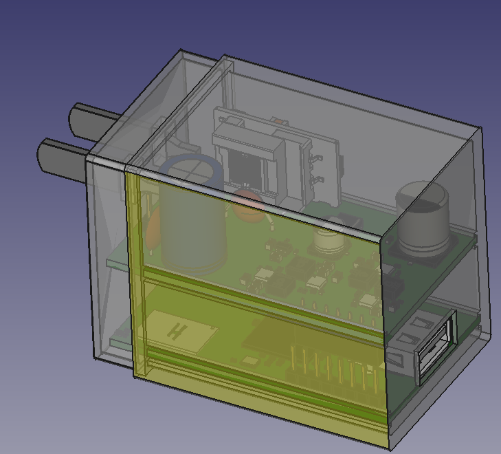
Up to this point, I’ve outlined a non-form-factor conception, design, assembly, bringup and characterization. Right now, I feel confident in the hardware and software, and I can begin the “form factor design”. Since the final design is the same electronics, I can be laser-focused on the mechanical aspects.
My goals are to have a fully functional and assembled unit with a 3D printed enclosure in the next post! To keep up to date with everything going on, I recommend joining the Discord server linked above!
Until next time! :)


