There are two classes of problems in the world: stupid and interesting. Building a fusion reactor is an interesting problem, while a thorn in your finger is a stupid problem. Typically you don’t like working on stupid problems. You want them gone. A job dealing with primarily stupid problems may be considered a shitty job. Currently, I’m working on some really stupid problems. Let’s read an email from my friend Mia.
As you know, the Texas IC components are tight supply, most components are out of stock, just some agents in market have limited inventory, but these agents seized this change to increase the cost maliciously, some IC components even increased 1000 times, but still hot selling. This is really bad situation for both of us. Fortunatelly, this IC still has 3000pcs in stock, but frankly speaking, cost is a little expensive, the unit price is 49.7usd/pcs based on EXW, and the quotation is valid for 3 days.
Mia is an electronics broker from Shenzhen; she hustles around components and connects engineers in North America to electronics dealers in Shenzhen. She is also trying to sell me a TI PMIC available on Digikey (3 months ago for $1.2) for $50. I’m using 4x of these PMICs on my board. You now see my problems; we are in a severe chip shortage.
Sourcing Electronics
Sourcing components for prototyping is usually straightforward; your CAD software will generate you a CSV BOM, you upload it to Digikey, and parts show up at your front door. I’ve gone through Mouser, Digikey, LCSC, Aliexpress, and my friend Mia to get parts for this build. You arrive at a costly prototype when you add up the combined shipping costs, parts costs, and duties.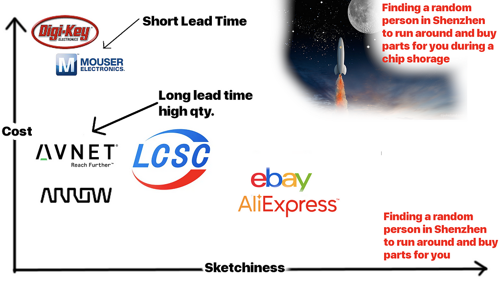
That’s enough complaining about the shortage; let’s talk about the power board design.
Power Board Design
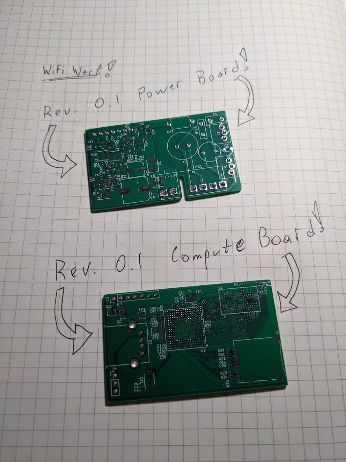
There are two boards in the design, they stack on top of each other, and both serve two separate functions. The compute board contains the SOC, RAM, SD card, USB and 2x wifi radios. The power board converts (100–300VAC) to 1.1V, 1.35V, 2.5V, 3.0V, 3.3V and 5VDC. It uses a flyback power module to do the mains to 5V conversion.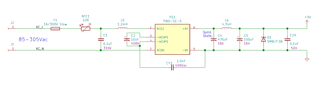
CUI has developed a nice part to do the heavy lifting; the PBO-5C-5 is a 5W AC to DC converter mounted in a SIP package. It can take anywhere from 80–300VAC and will output 5VDC. I chose this device for its UL certification. When designing a mains powered device, safety is always top of mind; a poorly designed device can catch fire. The CUI part comes with an integrated transformer, so I can sleep well knowing it has proper high/low side isolation.
Transformer Isolation
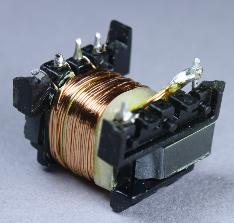
The device above is an example of a transformer with decent looking isolation. The yellow tape isolates the primary windings from the secondary windings. Poorly manufactured transformers will often omit this tape and have only the bronze-coloured lacquer wire coating as isolation. If the device overheats, this can cause a primary to secondary short, which would connect AC mains to the 5V USB port; at best, this would destroy a phone; at worst, it could be lethal.
PCB Isolation
The transformer isn’t the only item requiring decent isolation; the PCB should also be designed to allow acceptable creepage and clearance.
- Clearance is the shortest distance in air between two conductive parts.
- Creepage distance is the shortest distance along the surface of solid insulating material between two conductive parts.
You can google around and find a table of these recommended distances; I used IPC2221A. There are lots of different tables, most of which are similar.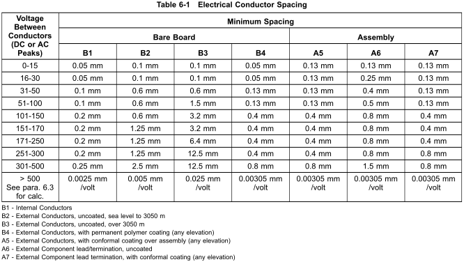
I just took 2.5mm and added another 1.5mm to be safe. 4 mm of isolation is very fair.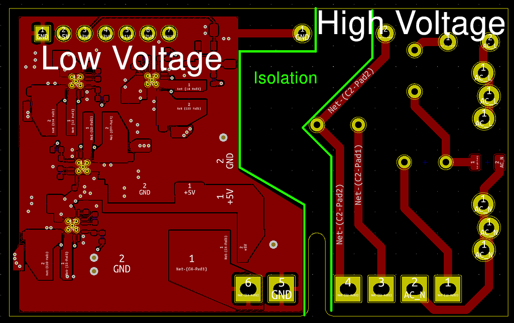
Line Bypass Capacitor
As for other safety components, let’s talk about some key players.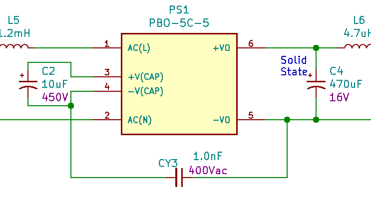
CY3 connects from the high to the low side. It exists to reduce electromagnetic interference. If it shorts out, it will connect AC mains to the 5V USB port. This is why we use class “Y1” rated capacitors, which will “fail open”.
Fusing
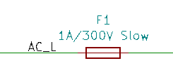
The fuse on the input ensures that if anything downstream fails, you’re not relying on the wall breaker (15A in North America) to trip out. It’s possible the device might short against a load that won’t cause to breaker to trip but will cause several amps of current to flow, which will start a fire.
NTC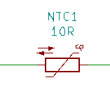
The negative temperature coefficient (NTC) device on the input limits inrush currents; when the device is powered up, NTC1 will have around 10ohms of resistance, raising the entire device’s input impedance, therefore limiting the device inrush current. After some time, the NTC1 will heat up, and the resistance will go down, reaching some equilibrium.
TVS Diode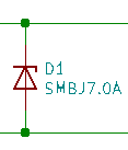
TVS diodes operate as transient overvoltage protection devices and are useful in highly inductive applications or devices that may experience static buildup during a plugin event. The diode has a reverse breakdown at a certain voltage, much like a zener, where it will start conducting.
In Conclusion
This certainly wasn’t my ideal post, but things are rocky right now. I plan to build some costly prototypes in the coming months, test and wait until things shake out on the chip shortage front.
I’m still very keen to run a crowdfunding campaign! However, I’ll have to press pause on that for now. Please keep in touch by joining our Discord community!