I’m building an open-source USB drive with a hidden self-destruct feature. Say goodbye to your data if you don’t lick your fingers before plugging it in. Its target customers are journalists in anti-privacy countries and security researchers.
This post outlines the design process and challenges. I’ll discuss my bench prototyping, the schematic, layout and mechanical sourcing.
A lot of the responses to the last post pointed out that the device doesn’t actually self-destruct. In response to these comments, the device will now have two modes: just hiding the data and a full self-destruct (FSD).
Enclosure
I found a shop overseas selling USB enclosures without the internals, which saves me from designing an enclosure from scratch. I’ve never designed an injection moulded enclosure before, and today won’t be the day.
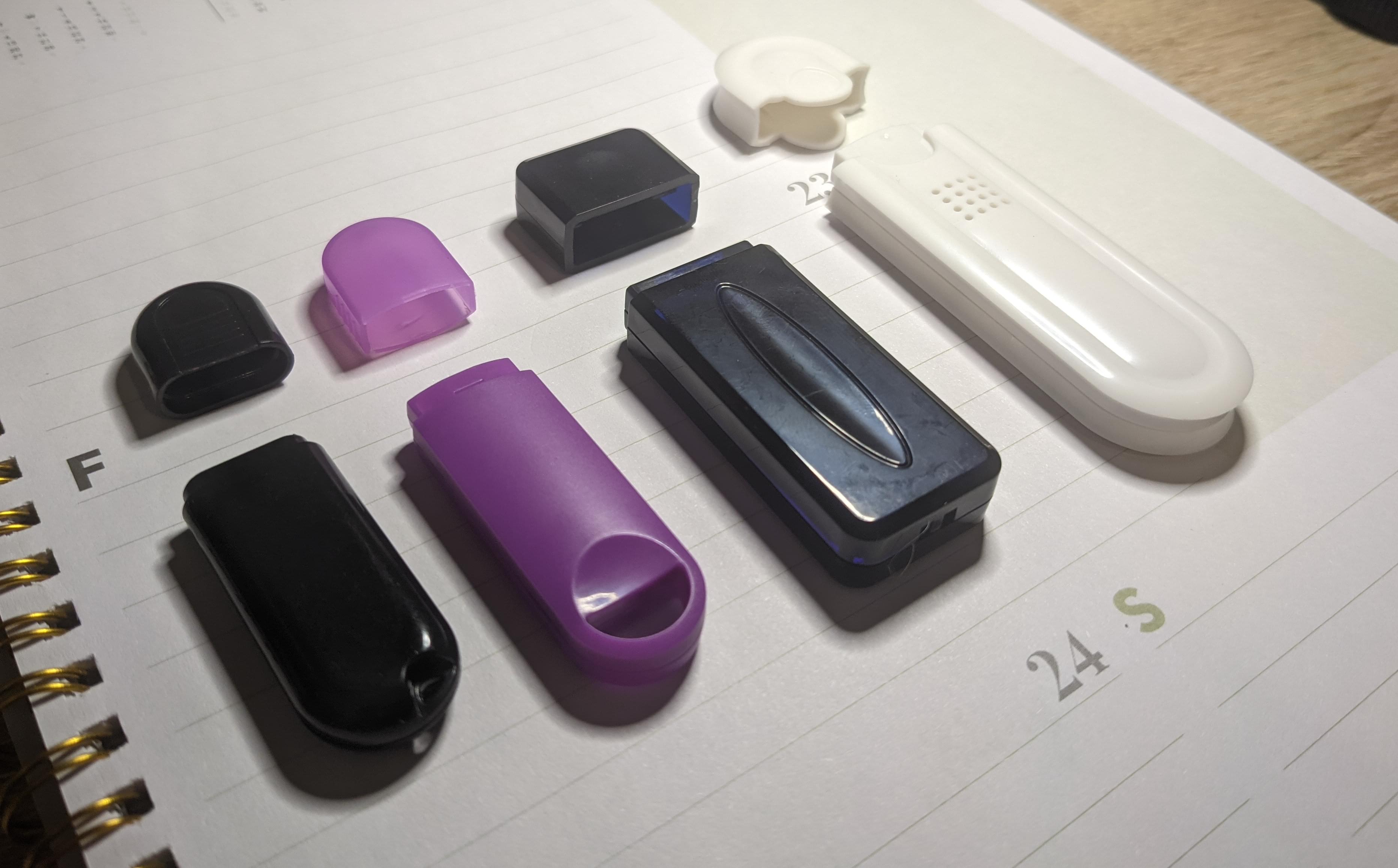
Out of the four samples I received, I settled on the black one (far left in the picture above). Unfortunately, the vendor could not give me 3D CAD files, just DXF. If you don’t know, DXF is a simple flat drawing; not ideal, but better than nothing.
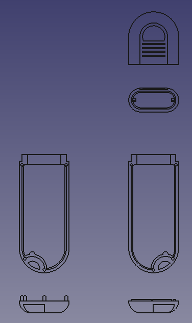
I took these DXF drawings, imported them into FreeCAD, and then extruded them into some 3D models. This was a strange way to draw a model; the DXF lines were converted to undimensioned FreeCAD sketch objects and then extruded. I imported the PCB and ended up here:
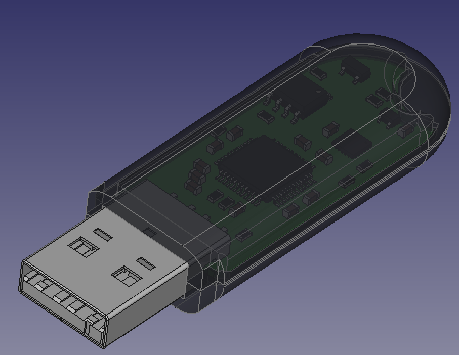
Hopefully, the final build will come out looking something like that.
FSD: Full Self Destruct
My goal is to build a discrete device; if the cops snatch a journalist in a non-privacy country, they shouldn’t think twice about a loose USB drive. When they plug it in, the device shouldn’t explode, melt, release corrosive material or do anything else insane (even though that would probably make a more exciting blog post). It should quietly destroy itself beyond repair.
My solution for this is overloading the flash memory voltage rail. I’ll have to say, this is the first time I’ve ever actually looked at the absolute maximum ratings of a component with the intent to go outside them.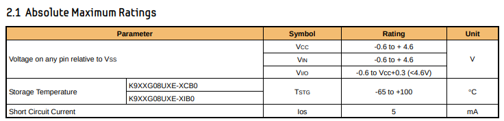
The part needs to be pushed over 4.6V in order to be completely disabled. I can use a simple voltage doubler off the 5V line to do this.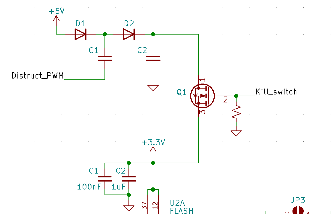
The operation of this circuit is pretty simple. When Distruct_PWM is low, Ca will charge to 4.3V, which is 5V minus the 0.7V drop over the diode. When I set Distruct_PWM high from the MCU, this puts the bottom of Ca at 5, giving a total potential of 9.3V. This flows into Cb and gets trapped for the next cycle. When you want to dump the energy into the flash IC, enable Q1 and say goodbye to those cute dog pics.
Sensing Circuit
OK, so how will the device know if the user has licked their fingers or not, and hence whether or not to destroy the data? This can be done with a bioimpedance measurement, i.e., a measurement of the resistance of the user’s skin. If the skin’s resistance is low (500k or less), we can assume their fingers are wet. There’s probably a fancy chip to measure bioimpedance, but since the chip shortage, I’ve been inclined to use generic components.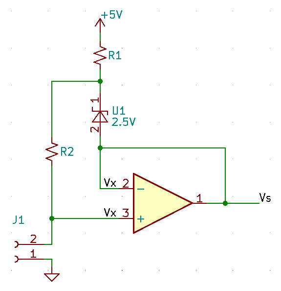
I pinched this circuit from The Art of Electronics; it’s a current supply. Let’s discuss how it works. U1 is a voltage reference; as long as it gets enough current to operate, there will be 2.5V dropped over it. The cathode is connected to R2, while the anode is connected to the non-inverting input of the opamp. The output of the opamp will supply the current required to hold the two inputs at the same voltage. Therefore we can assume there is 2.5V dropped over R2 as well. The current through R2 is then
Our electrodes are connected across J1, and the voltage at Vx and Vs is again determined by Ohm’s law:
So we can use these two equations to solve for the load resistance, RL:
This is what we’ll use to calculate skin resistance.
Microcontroller
I chose a simple attiny25 for the brains of the project. It’s a step down from the 32bit ARM chips I typically use. It was refreshing to fit the entire application into 55 lines of code with only one required header.
I configured a PWM channel to test the code. I read and ADC pin and output the voltage as a duty cycle on the PWM pin. Using my multimeter on DC mode, I read back the voltage I was sampling.
1 |
|
The Build
When working for a client, I don’t breadboard. It’s too expensive and doesn’t make sense with modern SMD components. My usual workflow is to go from simulation straight to schematic and board design. But for this project, I reached for the breadboard. I did this in order to derisk the bioimpedance circuit I discussed above. It felt like I was back in school again, nostalgic about DIP components and paper schematics.
The logic works fine. All of the learnings from this prototype were integrated into the final design.
The next and final post will be documenting the entire build, I’m hoping to then get a small crowdfunding campaign launched to build several of these devices for the community. Stay in touch and happy hacking!